Philips Semiconductors Product specification�
� Rectifier diodes BYQ30E, BYQ30EB, BYQ30ED series �
� ultrafast, rugged�
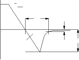
� Fig.1. Definition of trr1, Qs�
� and I�
� rrm�
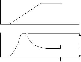
� Fig.2. Definition of Vfr�
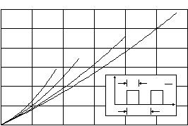
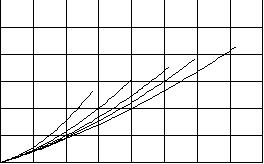
� Fig.3. Maximum forward dissipation PF�
� = f(I�
� F(AV)) per�
� diode; square current waveform where�
� IF(AV)�
� =I�
� F(RMS)�
� x �
� √D.�
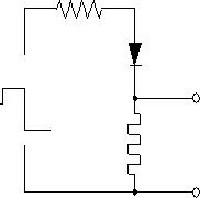
� Fig.4. Circuit schematic for trr2�
� Fig.5. Definition of trr2�
� Fig.6. Maximum forward dissipation PF�
� = f(I�
� F(AV)) per�
� diode; sinusoidal current waveform where a = form�
� factor = IF(RMS)�
� / I�
� F(AV).�
� Q�
� s�
� 100%�
� 10%�
� time�
� dI�
� F�
� dt�
� IR�
� I�
� F�
� Irrm�
� trr�
� shunt�
� Current�
� to 'scope�
� D.U.T.�
� Voltage Pulse Source�
� R�
� time�
� time�
� V�
� F�
� V�
� fr�
� V�
� F�
� I�
� F�
� I = 1AR�
� I = 0.25Arec�
� 0A�
� trr2�
� 0.5A�
� IF�
� IR�
� 0�
� 150�
� 024681012�
� 2�
� 4�
� 6�
� 8�
� Rs = 0.025 Ohms10�
� 12�
� Forward dissipation, PF (W)�
� Vo = 0.75 V�
� 0.5�
� 0.2�
� 0.1�
� BYQ30�
� Average forward current, IF(AV) (A)�
� Tmb(max) / C�
� D = 1.0�
� 114�
� 144�
� 138�
� 132�
� 126�
� 120�
� D = tpT�
� tp�
� T�
� t�
� I�
� 0�
� 150012345678�
� 2�
� 4�
� 6�
� 8�
� 10�
� Rs 0.025 Ohms�
� 12�
� Forward dissipation, PF (W)�
� a = 1.57�
� 1.9�
� 2.2�
� 2.8�
� 4�
� BYQ30�
� Vo = 0.75 V�
� Average forward current, IF(AV) (A)�
� Tmb(max) / C114�
� 144�
� 138�
� 132�
� 126�
� 120�
� October 1998 3 Rev 1.200�
�  �
�
� � �  �
�
� � �  �
�
� � �  �
�
� � �  �
�
� � �  �
�
� � �  �
�
� �  �
�
� � �  �
�
� � �  �
�
� � �  �
�
� � �  �
�
� � �  �
�
� � �  �
�
� � �  �
�
� � �  �
�
� � �  �
�
� � �  �
�
� � �  �
�
� � �  �
�
� � �  �
�
� � �  �
�
� � �  �
�
� � �  �
�
� � �  �
�
� � �  �
�
� � �  �
�
� � �  �
�
� � �  �
�
� � 发布紧急采购,3分钟左右您将得到回复。
相关PDF资料
BYT28F-400HE3/45
DIODE DUAL 10A 400V TO-263AB
BYV32-200G
DIODE ULT FAST 200V 8A TO-220AB
BYV32E-150,127
DIODE RECT 150V 20A SOT78
BYV32EB-200,118
DIODE RECT UFAST 200V D2PAK
BYV32G-200,127
DIODE RECT UFAST 200V I2PAK
BYV34-600,127
DIODE RECT DUAL 600V 20A TO220AB
BYV34G-600,127
DIODE RECT DUAL 600V 20A I2PAK
BYV410X-600,127
DIODE RECT UFAST DL 600V TO220-3
相关代理商/技术参数
byq30e-200127
制造商:NXP 功能描述: 制造商:NXP Semiconductors 功能描述:
BYQ30EB
制造商:PHILIPS 制造商全称:NXP Semiconductors 功能描述:Rectifier diodes ultrafast, rugged
BYQ30EB-100
制造商:PHILIPS 制造商全称:NXP Semiconductors 功能描述:Rectifier diodes ultrafast, rugged
BYQ30EB-150
制造商:PHILIPS 制造商全称:NXP Semiconductors 功能描述:Rectifier diodes ultrafast, rugged
BYQ30EB-200
制造商:PHILIPS 制造商全称:NXP Semiconductors 功能描述:Rectifier diodes ultrafast, rugged
BYQ30EBSERIES
制造商:PHILIPS 制造商全称:NXP Semiconductors 功能描述:Rectifier diodes ultrafast. rugged
BYQ30ED
制造商:PHILIPS 制造商全称:NXP Semiconductors 功能描述:Rectifier diodes ultrafast, rugged
BYQ30ED-100
制造商:PHILIPS 制造商全称:NXP Semiconductors 功能描述:Rectifier diodes ultrafast, rugged